This page is under development for the TONEWHEELS project, as part of a residency at the Tesla media arts laboratory, in Berlin, Germany over the months of Oct-Dec 2007, and at STEIM during the last two weeks of February 2008, and I am grateful for their support. Further technical support was provided by Martin Howse, Jeff Mann and Manfred Fox in Berlin, and Marc Boon in Amsterdam.
CONTACT
derek ___AT THE DOMAIN___ umatic.nl

AN INTRODUCTION TO THE TECHNOLOGY OF OPTICAL SYNTHESIS
INTRODUCTION
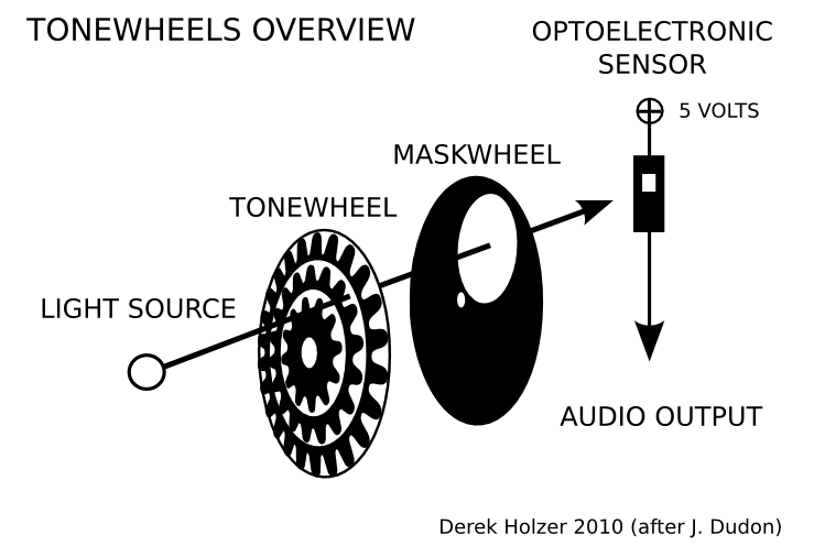
The astonishingly simple
technology employed by the
TONEWHEELS project creates
sound directly from light by
means of an optoelectronic
sensor. In the diagram above, a LIGHT SOURCE is
directed through two
transparent, spinning disks.
The first disk, the TONEWHEEL,
has patterns representing sound
waves printed on it. This disk
modulates the light in a similar
manner as the optical
soundtrack of 16mm and 35mm
motion picture film. The tone
produced depends on both the
number of peaks printed on the
disk, and the speed at which
the disk rotates.
After the first TONEWHEEL, any number of secondary MASKWHEELS may be used to
further filter or modulate the light before it reaches the sensor. These MASKWHEELS
create the same kind of amplitude modulation as the low-frequency oscillators in
analog synthesizers, and are heard as anything from a rhythmic pulse to additional
sonic frequencies.
Once the light has passed through these various wheels, it falls on the
OPTOELECTRONIC SENSOR, typically a phototransistor or photodiode. This sensor
allows five volts of direct electrical current to pass through when exposed to light,
and blocks the current when in shadow. From there, the modulated current may be
used as an audio signal by connecting the AUDIO OUTPUT to an amplifier and
speaker, or it may be sent through a mixer and various other electronic effects for
further treatment.
TONEWHEELS ELECTRONICS

Simple parts are all that are needed to explore optical sound.

Using a phototransistor to modulate the voltage from a battery is the simplest method. This can be connected directly to a speaker, or to some types of mixer channels or amps (line level usually).

To drive multiple phototransistors with a minimum of crosstalk between the channels, a voltage regulator and a few capacitors can provide a stabilized source of voltage to the transistors. Here, jack cables are used to connect the circuit to a mixer via the line inputs.
In order to connect this circuit to many types of audio equipment (mixer inputs, guitar effects, modular synthesizers, etc etc), it is necessary to create an output buffer. Buffers are simple circuits, often using one or more op-amps, which act as the middle-man and help other circuits talk to each other in the the world of electronics.
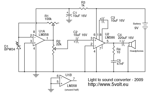
The light to sound converter circuit above was designed by Alex at 5volt.eu.
It uses a BPW34 photodiode instead of a phototransistor, and the diode makes a connection to ground rather than to power. That is followed by U1, which uses an LM358 op-amp chip as the buffer. The op-amp is configured as an inverting op-amp, which means it will give positive voltage at the output (pin 1) when it sees a connection to ground at the inverting input (pin 2).
R1 is a potentiometer, which controls the threshold of the op-amp. This means that you can adjust the circuit to the contrast between light and shadow in order to give the strongest signal out. R2 is another potentiometer, which controls the output volume, and C2 is a capacitor which blocks any DC voltage (the constant part of the signal, rather than the part which is AC--the audio part) from going further in the circuit. If you plan to connect this circuit to a mixer, then an output jack can be inserted between C2 and pin 3 of U2, the LM386 amplifier.
The LM386 amplifier chip is used to drive either a speaker or a pair of headphones. This amp has a nasty tendency to self-oscillate, meaning that it produces a tone all by itself. This can be prevented by making sure there are no "ground loops" in the circuit. In other words, each connection in the diagram which leads to the bottom-most line has only a single path or wire leading there, instead of several paths to ground.
Please see Alex's site for more discussion about this light-to-sound converter.
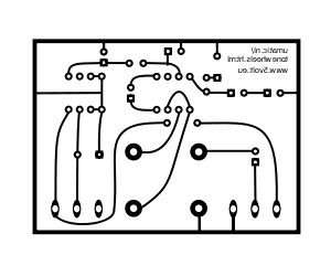
I have designed a Printed Circuit Board for this circuit, with an added output jack for connecting to a mixer, here:
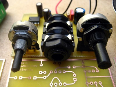
And here is a photo of the completed project:
NOTICE: in order to keep the headphone/speaker amp in this circuit from self-oscillating, it may be necessary to make a cut in the copper at the upper left hand corner of the border of the PCB, just next to the printed text when looking at the copper side of the etched board. This is to prevent a ground loop, as mentioned above. This should not be a problem when the jack ouput is used to connect the circuit to a mixer or other device.
COMING SOON: updated PCB to fix self-oscillation problem of the amplifier. When PCB is updated, I will also include a parts mask here so you know which components go in which holes!
MOTOR ELECTRONICS
In order to control the speed of the motor which spins the TONEWHEEL in front of the optoelectronic sensor, I use this Pulse Width Modulation Motor Speed Controller designed by G. Forrest Cook at Solorb.com:
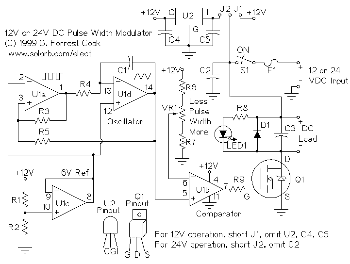
Parts
U1: LM324N quad op-amp
U2: 78L12 12 volt regulator
Q1: IRF521 N channel MOSFET
D1: 1N4004 silicon diode
LED1: Red LED
C1: 0.01uF ceramic disc capacitor, 25V
C2-C5: 0.1uF ceramic disk capacitor, 50V
R1-R4: 100K 1/4W resistor
R5: 47K 1/4W resistor
R6-R7: 3.3K 1/4W resistor
R8: 2.7K 1/4W resistor
R9: 470 ohm 1/4W resistor
VR1: 10K linear potentiometer
F1: 3 Amp, 28V DC fast blow fuse
S1: toggle switch, 5 Amps
Please note that I power this circuit with a 12V wall power supply. It is not recommended to use the same power supply for the motors and the light-to-sound converter, as the motor controller produces a lot of electric noise due to the pulse width modulation of the current to the motor.
Mr. Cook has also kindly provided the PCB artwork for this circuit, as well as the parts placement mask:
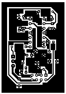
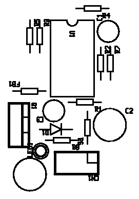
Silkscreen clarifications: the unlabeled circular pattern near LED1 is a wire jumper and the part labeled FB1 is really R9.
The connections for the 8 pin header on the printed circuit board are as follows:
Header layout as oriented in PCB artwork:
7 5 3 1
8 6 4 2
1: VR1 clockwise
2: VR1 counter clockwise
3: 12V Supply + and Load +
4: VR1 wiper
5: 12V Supply + and Load +
6: 12V Supply -
7: Load -
8: 12V Supply -
Please refer to G. Forrest Cook's site for more information on this circuit.
ACKNOWLEDGEMENTS
TONEWHEELS was conceived during the "Kunst & Musik mit dem Tageslichtprojektor" workshop at the Moltkerei (Cologne, DE), organized by Ralph Schreiber, Christian Faubel and Tina Tongerel. TONEWHEELS had it's first full-scale premier at the Passengers International Festival of Public Art (Warsaw, PL).
Derek Holzer
Berlin, October 2007 (updated Feb 2010)
TONEWHEELS
> PERFORMANCE
> TECHNICAL
> HISTORY